US5331288A - Railroad rail signal receiver having frequency conversion and a resonant tuned transformer secondary - Google Patents
Railroad rail signal receiver having frequency conversion and a resonant tuned transformer secondary Download PDFInfo
- Publication number
- US5331288A US5331288A US07/673,025 US67302591A US5331288A US 5331288 A US5331288 A US 5331288A US 67302591 A US67302591 A US 67302591A US 5331288 A US5331288 A US 5331288A
- Authority
- US
- United States
- Prior art keywords
- receiver
- signal
- winding
- frequency
- higher frequency
- Prior art date
- Legal status (The legal status is an assumption and is not a legal conclusion. Google has not performed a legal analysis and makes no representation as to the accuracy of the status listed.)
- Expired - Fee Related
Links
Images
Classifications
-
- B—PERFORMING OPERATIONS; TRANSPORTING
- B61—RAILWAYS
- B61L—GUIDING RAILWAY TRAFFIC; ENSURING THE SAFETY OF RAILWAY TRAFFIC
- B61L1/00—Devices along the route controlled by interaction with the vehicle or vehicle train, e.g. pedals
- B61L1/18—Railway track circuits
- B61L1/181—Details
Definitions
- This invention relates to a vital apparatus for receiving signals transmitted over railroad rails. It is more particularly concerned with vital receivers having low impedance for such purpose.
- This invention provides a vital receiver by using a frequency converter to change the signal from the rail to a higher frequency alternating signal.
- this frequency converter can be a solid state chopper device which will convert either DC or pulsed DC into a higher frequency alternating polarity pulsed signal.
- AC track signals can be converted to a higher frequency signal using similar solid state frequency conversion circuitry.
- This converted higher frequency signal is then fed to an input transformer.
- the output of the transformer is fed into a tuned circuit.
- the tuned circuit uses the input transformer's secondary along with discrete components and the primary winding inductance of an output transformer to form a tuned circuit that has as its resonant frequency the same higher frequency which has previously been converted.
- the input transformer provides impedance matching to the desired low impedance seen from the rails.
- the resonant circuit components can be selected from resistances, capacitance, or inductance as required to meet the specific impedance and frequencies of a given circuit.
- One of the components in the resonant circuit includes the primary of an output transformer.
- the output transformer provides isolation and impedance matching between the high frequency signal in the resonant circuitry and the output.
- the output from the secondary of the output transformer can be used to sense the track signal. Because of the series arrangement of components and the necessity to match impedance, failures in the receiver which raise the impedance presented to the rails will also cause a corresponding decrease in the signal at the output.
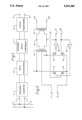
- FIG. 1 is a block diagram of one presently preferred embodiment of the invention.
- FIG. 2 is a circuit diagram of a presently preferred embodiment of the invention using solid state switching, and a series resistor and capacitor as resonant circuit components.
- FIG. 1 is shown a set of rails 1 and 2 which have superimposedthereon the signal which it is desired to receive.
- the signal is brought toterminals 3 and 4 of a frequency converter device 5. While the FIG. 1 circuit shows a direct connection, other known means of delivering the signal to the receiver can be used. In addition, while no transformer is shown coupling the rails to terminals 3 and 4, it is understood that in some embodiments this will be a preferred method to deliver a signal to the receiver.
- the track signal available to terminals 3 and 4 is then converted into a higher frequency bipolar signal by a frequency converter 5.
- the frequency converter in the presentlypreferred embodiments could be an inverting DC chopper device having an output frequency greater than a thousand Hertz and in some embodiments outputs from DC choppers having a frequency of the order of magnitude of 10K Hertz have been contemplated.
- the output frequency chosen will depend upon the component design requirements for a specific installation.
- the high frequency output of the converter 5 is then fed to an input transformer 6.
- resonant circuit components 7 which are selected to provide the resonant frequency in the secondary of the input transformer 6, including the inductances and resistances in both input and output transformers 6 and 8 to resonate at the fixed frequency as converted by the frequency converter 5.
- the secondary of the output transformer 8 is then delivered to the receiver output terminals 9 and 10.
- the rails signal has been a pulsed DC coded signal and the frequency converter 5 hasbeen an inverting DC chopper, then if the output at terminals 9 and 10 are fed to a full wave rectifying bridge circuit, the result will be a reconstruction of the original track circuit without the converted higher frequency present.
- the rail signal is delivered to input terminals 11 and 12.
- the input signal from the track is a coded DC signal having a frequency of approximately 5 Hertz.
- This low frequency pulsed DC signal is then converted into a higher frequency alternating signal by means of a solid state inverting chopper using solid state switching elements 13, 14, 15, and 16.
- a gating signal of the desired high frequency is applied to terminals 17 and 18.
- Such a signal typically could be 10K Hertz.
- the solid state switches 13, 14, 15, and 16, field effect transistors in presently preferred embodiments, are gated by appropriate signals and phase relationship from inverters 19 and 20.
- This bridge circuit then feeds the primary winding of input transformer 21, in a center tap arrangement.
- field effect transistors devices for chopping switches 13, 14, 15, and 16 which are available with "on" resistances of only a few hundredths of an ohm. Because these devices have an inherent built-in reverse diode from drain to source, if an AC signal isto be chopped, they must be used in series pairs, back-to-back. Other frequency converting circuits or chopping devices can be used to practice this invention.
- a center tap transformer 21 is used withthe input transformer 21, other transformer arrangements are equally applicable. Input transformer 21 acts to reflect the load impedance of thesecondary circuit as seen by the rails by the square of the turns ratio.
- the impedance in the secondary circuit of the input transformer 21 includes the series arrangement of resistor 23, capacitor 22, and the respective impedance of the windings of transformers 21 and 24.
- the load presented to the input terminals 11, 12 is primarily determined by the turns ratio of input transformer 21 and the value of the impedance in the secondary of input transformer 21.
- Resistor 23 can be selected to be the primary determining factor of the secondary impedance so that the impedance can be accurately controlled.
- Resistor 23 can have a high value relative to the other series impedance in the secondary of input transformer 21. Since the signal from the track circuit will normally be reconstructed at the terminals 25, 26 of the receiver, it is desirable to have transformers 21 and 24 act as linearly as possible.
- Changes in value of capacitor 22 causes the circuit to be out of tune and result in a reduction of signal delivered to terminals 25,26.
- the impedance of the resonant circuit including the series impedance ofcapacitor 22, resistor 23, and the respective windings of transformers 21 and 24 cannot rise without a decrease in the output signal across terminals 25 and 26.
- failures of components on the input side of transformer 21 such as switch devices 13, 14, 15, 16, causes a reduction in the signal strength or frequency to transformer 21, which in turn results in a reduced output at terminals 25 and 26.
- the invention is also practiced with AC rail signals.
- the frequency converter merely changes the AC signal into a predetermined higher frequency.
- the output can either be used at the higher frequency or converted back to the lower rail frequency.
Abstract
A receiver for use in receipt of signals on railroad rails which converts the rail signal to a higher frequency and feeds the higher frequency signal into an input transformer. The secondary of the input transformer is in a tuned circuit which is resonate at the higher frequency and which contains a winding of an output transformer. The tuned circuit can be tuned to the higher frequency by series components such as a resistor and capacitor.
Description
1. Field of the Invention
This invention relates to a vital apparatus for receiving signals transmitted over railroad rails. It is more particularly concerned with vital receivers having low impedance for such purpose.
2. Description of Prior Art
Communication over railroad rails using electrical signals had been accomplished using direct current, coded direct current or alternating current. Receivers to detect or decode such signals may be located on locomotives, transit vehicles, or wayside, wherever it is desired to interface with such rail signals. Steady state direct current permits transmission of only one piece of information; coded DC or AC can accommodate many specific communications. Where communication over distances as great as several miles is desired, the high and variable losses in rail transmission lines requires signals of very low frequencies such as 2 to 10 Hertz. It is fairly often desired to use track receivers in track circuits where the loss of detection of such signals is an indication that either the track is occupied or that the rail is broken. Because of variations and transmission losses in rail-to-rail impedance caused by ballast conditions, it is necessary to use a receiving device of extremely low impedance, usually under 1 ohm. It is essential for safety considerations that detection be free from ambiguity; therefore, the input impedance of the receiver must not, as the result of any component failure, have an increased input impedance without a corresponding loss in sensitivity. A conventional receiver with input shunted by a resistor would be unsafe if the resistor or its wiring should open because its input impedance would increase and the receiver sensitivity would also increase.
This invention provides a vital receiver by using a frequency converter to change the signal from the rail to a higher frequency alternating signal. In the case of DC this frequency converter can be a solid state chopper device which will convert either DC or pulsed DC into a higher frequency alternating polarity pulsed signal. Similarly AC track signals can be converted to a higher frequency signal using similar solid state frequency conversion circuitry. This converted higher frequency signal is then fed to an input transformer. The output of the transformer is fed into a tuned circuit. The tuned circuit uses the input transformer's secondary along with discrete components and the primary winding inductance of an output transformer to form a tuned circuit that has as its resonant frequency the same higher frequency which has previously been converted. In addition to acting as part of the resonant circuitry, the input transformer provides impedance matching to the desired low impedance seen from the rails. The resonant circuit components can be selected from resistances, capacitance, or inductance as required to meet the specific impedance and frequencies of a given circuit. One of the components in the resonant circuit includes the primary of an output transformer. The output transformer provides isolation and impedance matching between the high frequency signal in the resonant circuitry and the output. The output from the secondary of the output transformer can be used to sense the track signal. Because of the series arrangement of components and the necessity to match impedance, failures in the receiver which raise the impedance presented to the rails will also cause a corresponding decrease in the signal at the output.
FIG. 1 is a block diagram of one presently preferred embodiment of the invention.
FIG. 2 is a circuit diagram of a presently preferred embodiment of the invention using solid state switching, and a series resistor and capacitor as resonant circuit components.
Referring to FIG. 1 is shown a set of rails 1 and 2 which have superimposedthereon the signal which it is desired to receive. The signal is brought toterminals 3 and 4 of a frequency converter device 5. While the FIG. 1 circuit shows a direct connection, other known means of delivering the signal to the receiver can be used. In addition, while no transformer is shown coupling the rails to terminals 3 and 4, it is understood that in some embodiments this will be a preferred method to deliver a signal to the receiver. The track signal available to terminals 3 and 4 is then converted into a higher frequency bipolar signal by a frequency converter 5. If the track signals were DC or coded DC, having a typical low frequency less than 10 Hertz then the frequency converter in the presentlypreferred embodiments could be an inverting DC chopper device having an output frequency greater than a thousand Hertz and in some embodiments outputs from DC choppers having a frequency of the order of magnitude of 10K Hertz have been contemplated. The output frequency chosen will depend upon the component design requirements for a specific installation. The high frequency output of the converter 5 is then fed to an input transformer 6. Between the input transformer 6 and the output transformer 8 are resonant circuit components 7 which are selected to provide the resonant frequency in the secondary of the input transformer 6, including the inductances and resistances in both input and output transformers 6 and 8 to resonate at the fixed frequency as converted by the frequency converter 5. The secondary of the output transformer 8 is then delivered to the receiver output terminals 9 and 10. In the case where the rails signal has been a pulsed DC coded signal and the frequency converter 5 hasbeen an inverting DC chopper, then if the output at terminals 9 and 10 are fed to a full wave rectifying bridge circuit, the result will be a reconstruction of the original track circuit without the converted higher frequency present.
Further details of the circuitry and the components are shown in FIG. 2. The rail signal is delivered to input terminals 11 and 12. For an analysisof the circuit of FIG. 2 it will be assumed that the input signal from the track is a coded DC signal having a frequency of approximately 5 Hertz. This low frequency pulsed DC signal is then converted into a higher frequency alternating signal by means of a solid state inverting chopper using solid state switching elements 13, 14, 15, and 16. A gating signal of the desired high frequency is applied to terminals 17 and 18. Such a signal typically could be 10K Hertz. The solid state switches 13, 14, 15, and 16, field effect transistors in presently preferred embodiments, are gated by appropriate signals and phase relationship from inverters 19 and 20. The output of this bridge circuit then feeds the primary winding of input transformer 21, in a center tap arrangement. In presently preferred embodiments it is desirable to use field effect transistors devices for chopping switches 13, 14, 15, and 16 which are available with "on" resistances of only a few hundredths of an ohm. Because these devices havean inherent built-in reverse diode from drain to source, if an AC signal isto be chopped, they must be used in series pairs, back-to-back. Other frequency converting circuits or chopping devices can be used to practice this invention. In addition while a center tap transformer 21 is used withthe input transformer 21, other transformer arrangements are equally applicable. Input transformer 21 acts to reflect the load impedance of thesecondary circuit as seen by the rails by the square of the turns ratio. The impedance in the secondary circuit of the input transformer 21 includes the series arrangement of resistor 23, capacitor 22, and the respective impedance of the windings of transformers 21 and 24. The load presented to the input terminals 11, 12 is primarily determined by the turns ratio of input transformer 21 and the value of the impedance in the secondary of input transformer 21. Resistor 23 can be selected to be the primary determining factor of the secondary impedance so that the impedance can be accurately controlled. Resistor 23 can have a high value relative to the other series impedance in the secondary of input transformer 21. Since the signal from the track circuit will normally be reconstructed at the terminals 25, 26 of the receiver, it is desirable to have transformers 21 and 24 act as linearly as possible.
As can be seen in FIG. 2 any failure which would increase the impedance presented to the rails, at terminals 11, 12, such as an increase in resistance of the resistor 23, or an open or short of the capacitor 22, would cause a corresponding change in the output, secondary, of transformer 24. Changes in value of capacitor 22 causes the circuit to be out of tune and result in a reduction of signal delivered to terminals 25,26. The impedance of the resonant circuit including the series impedance ofcapacitor 22, resistor 23, and the respective windings of transformers 21 and 24 cannot rise without a decrease in the output signal across terminals 25 and 26. Similarly, failures of components on the input side of transformer 21 such as switch devices 13, 14, 15, 16, causes a reduction in the signal strength or frequency to transformer 21, which in turn results in a reduced output at terminals 25 and 26.
While the above embodiment has been described with regard to a rail signal that is preferably coded DC, the invention is also practiced with AC rail signals. The frequency converter merely changes the AC signal into a predetermined higher frequency. The output can either be used at the higher frequency or converted back to the lower rail frequency.
While certain embodiments of the invention have been described herein, it is to be understood that other practices of the invention are included within the scope of the following claims.
Claims (25)
1. A receiver for reception of signals transmitted on railroad rails comprising:
frequency converter means for converting the frequency of said signal into a higher frequency signal;
an input transformer having a primary winding electrically connected to said frequency converter means to conduct said higher frequency signal in said primary winding;
the secondary winding of said input transformer connected as an active circuit element of a resonant circuit having a resonant frequency generally equal to the frequency of said higher frequency signal; and
an output transformer having a first winding and a second winding, said first winding being an active circuit element in said resonant circuit and said second winding mechanically coupled to said first winding to provide an output signal corresponding to said higher frequency signal.
2. The receiver of claim 1 wherein said resonant circuit further includes at least one circuit component in series with said secondary winding of said input transformer and said first winding of said output transformer.
3. The receiver of claim 2 wherein said circuit component comprises a capacitor.
4. The receiver of claim 3 wherein said circuit component further comprises a resistor.
5. The receiver of claim 2 wherein said circuit component further comprises a resistor.
6. The receiver of claim 1 wherein said frequency converter means includes solid state switching means for switching said signal at said higher frequency.
7. The receiver of claim 6 wherein said solid state switching means alternates the polarity of said signal at said higher frequency.
8. The receiver of claim 6 wherein said resonant circuit further includes at least one circuit component in series with said secondary winding of said input transformer and said first winding of said output transformer.
9. The receiver of claim 8 wherein said circuit component further comprises a resistor.
10. The receiver of claim 8 wherein said circuit component comprises a capacitor.
11. The receiver of claim 7 wherein said resonant circuit further includes at least one circuit component in series with said secondary winding of said input transformer and said first winding of said output transformer.
12. The receiver of claim 11 wherein said resonant circuit further comprises a resistor.
13. The receiver of claim 12 wherein said circuit component comprises a capacitor.
14. The receiver of claim 1 wherein said signal is a coded DC signal;
said frequency converter means includes solid state switching means for switching said signal at said higher frequency; and
said solid state switching means alternates the polarity of said signal at said higher frequency.
15. The receiver of claim 14 wherein said resonant circuit further comprises a series resistor.
16. The receiver of claim 15 wherein said resonant circuit further includes at least one circuit component in series with said secondary winding of said input transformer and said first winding of said output transformer; and
said circuit component comprises a capacitor.
17. The receiver of claim 14 wherein said resonant circuit further includes at least one circuit component in series with said secondary winding of said input transformer and said first winding of said output transformer; and
circuit component comprises a capacitor.
18. The receiver of claim 14 wherein said coded DC signal has a frequency of generally less than 10 Hertz.
19. The receiver of claim 14 wherein said higher frequency is generally in the range from 5K Hertz to 50K Hertz.
20. The receiver of claim 18 wherein said higher frequency is generally in the range from 5K Hertz to 50K Hertz.
21. A receiver for reception of signals transmitted on railroad rails comprising:
frequency converter means for converting the frequency of said signal into a higher frequency signal;
an input transformer having a primary winding electrically connected to said frequency converter means to conduct said higher frequency signal in said primary winding;
the secondary winding of said input transformer connected as an active circuit element on a resonant circuit having a resonant frequency generally equal to the frequency of said higher frequency signal;
an output transformer having a first winding and a second winding, said first winding being an active circuit element in said resonant circuit and said second winding magnetically coupled to said first winding to provide an output signal corresponding to said higher frequency signal;
said frequency converter means includes solid state switching means for switching said signal at said higher frequency;
said solid state switching means alternates the polarity of said signal at said higher frequency; and
said solid state switching means includes two pairs of field effect transistors connected in a chopper circuit, each pair having one of said transistors having a gate controlled by a switching signal and the other of said transistors having a gate controlled by said switching signal through an inverter.
22. The receiver of claim 7 wherein said resonant circuit further comprises at least one circuit component in series with said secondary winding of said input transformer and said first winding of said output transformer.
23. The receiver of claim 22 wherein said circuit component includes a resistor and capacitor.
24. The receiver of claim 23 wherein said signal is a coded DC signal having a frequency of generally less than 10 Hertz.
25. The receiver of claim 24 wherein said higher frequency is generally in the range from 5K Hertz to 50K Hertz.
Priority Applications (3)
| Application Number | Priority Date | Filing Date | Title |
|---|---|---|---|
| US07/673,025 US5331288A (en) | 1991-03-21 | 1991-03-21 | Railroad rail signal receiver having frequency conversion and a resonant tuned transformer secondary |
| CA002054315A CA2054315C (en) | 1991-03-21 | 1991-10-28 | Railroad rail signal receiver |
| MX9102301A MX9102301A (en) | 1991-03-21 | 1991-11-29 | SIGNAL RECEIVER FOR RAILWAY RAILS. |
Applications Claiming Priority (1)
| Application Number | Priority Date | Filing Date | Title |
|---|---|---|---|
| US07/673,025 US5331288A (en) | 1991-03-21 | 1991-03-21 | Railroad rail signal receiver having frequency conversion and a resonant tuned transformer secondary |
Publications (1)
| Publication Number | Publication Date |
|---|---|
| US5331288A true US5331288A (en) | 1994-07-19 |
Family
ID=24701015
Family Applications (1)
| Application Number | Title | Priority Date | Filing Date |
|---|---|---|---|
| US07/673,025 Expired - Fee Related US5331288A (en) | 1991-03-21 | 1991-03-21 | Railroad rail signal receiver having frequency conversion and a resonant tuned transformer secondary |
Country Status (3)
| Country | Link |
|---|---|
| US (1) | US5331288A (en) |
| CA (1) | CA2054315C (en) |
| MX (1) | MX9102301A (en) |
Cited By (5)
| Publication number | Priority date | Publication date | Assignee | Title |
|---|---|---|---|---|
| US20060214067A1 (en) * | 2005-02-08 | 2006-09-28 | Stefano Orlandi | Railway power supply system and method for powering an electrical device situated along a railway |
| US9102341B2 (en) | 2012-06-15 | 2015-08-11 | Transportation Technology Center, Inc. | Method for detecting the extent of clear, intact track near a railway vehicle |
| US9162691B2 (en) | 2012-04-27 | 2015-10-20 | Transportation Technology Center, Inc. | System and method for detecting broken rail and occupied track from a railway vehicle |
| RU170723U1 (en) * | 2016-10-03 | 2017-05-04 | Ханан Григорьевич Офенгейм | DEVICE FOR INSTALLING THROTTLE TRANSFORMER |
| RU209183U1 (en) * | 2021-11-17 | 2022-02-04 | Открытое акционерное общество "Объединенные электротехнические заводы" | Device for installing a choke-transformer |
Citations (15)
| Publication number | Priority date | Publication date | Assignee | Title |
|---|---|---|---|---|
| US1975371A (en) * | 1932-12-10 | 1934-10-02 | Union Switch & Signal Co | Electric signaling system |
| US2019166A (en) * | 1934-02-17 | 1935-10-29 | Union Switch & Signal Co | Electric train signaling system |
| US2029396A (en) * | 1934-07-11 | 1936-02-04 | Union Switch & Signal Co | Apparatus for communication systems |
| US2032725A (en) * | 1933-12-16 | 1936-03-03 | Union Switch & Signal Co | Communication system |
| US2129313A (en) * | 1935-07-01 | 1938-09-06 | Union Switch & Signal Co | Apparatus for electric signaling systems |
| US2534746A (en) * | 1946-02-01 | 1950-12-19 | Frank H Wells | Decoder |
| US2828363A (en) * | 1952-09-25 | 1958-03-25 | Westinghouse Electric Corp | Carrier current communication system |
| US2947814A (en) * | 1957-12-27 | 1960-08-02 | Gen Railway Signal Co | Carrier transmitter |
| US3021506A (en) * | 1957-03-25 | 1962-02-13 | Gen Railway Signal Co | Communication system |
| US3634728A (en) * | 1970-07-13 | 1972-01-11 | Jeumont Schneider | Current chopper for dc machines connected to the terminals of a source having an inductive impedance |
| US3639819A (en) * | 1968-11-27 | 1972-02-01 | Jeumont Schneider | Switcher-chopper for controlling current in brushless rotating machines, supplied by a dc source |
| US3946972A (en) * | 1975-05-08 | 1976-03-30 | Westinghouse Air Brake Company | Simplified cab signal receiver circuit |
| US4298179A (en) * | 1979-05-31 | 1981-11-03 | American Standard Inc. | Vital cross field transformer circuit arrangement for railroad signaling systems |
| US4392626A (en) * | 1981-09-14 | 1983-07-12 | American Standard Inc. | Vital protection arrangement for railroad track circuits |
| US4535959A (en) * | 1982-08-02 | 1985-08-20 | American Standard Inc. | Vital solid state relay for railroad alternating current track circuits |
-
1991
- 1991-03-21 US US07/673,025 patent/US5331288A/en not_active Expired - Fee Related
- 1991-10-28 CA CA002054315A patent/CA2054315C/en not_active Expired - Fee Related
- 1991-11-29 MX MX9102301A patent/MX9102301A/en not_active IP Right Cessation
Patent Citations (15)
| Publication number | Priority date | Publication date | Assignee | Title |
|---|---|---|---|---|
| US1975371A (en) * | 1932-12-10 | 1934-10-02 | Union Switch & Signal Co | Electric signaling system |
| US2032725A (en) * | 1933-12-16 | 1936-03-03 | Union Switch & Signal Co | Communication system |
| US2019166A (en) * | 1934-02-17 | 1935-10-29 | Union Switch & Signal Co | Electric train signaling system |
| US2029396A (en) * | 1934-07-11 | 1936-02-04 | Union Switch & Signal Co | Apparatus for communication systems |
| US2129313A (en) * | 1935-07-01 | 1938-09-06 | Union Switch & Signal Co | Apparatus for electric signaling systems |
| US2534746A (en) * | 1946-02-01 | 1950-12-19 | Frank H Wells | Decoder |
| US2828363A (en) * | 1952-09-25 | 1958-03-25 | Westinghouse Electric Corp | Carrier current communication system |
| US3021506A (en) * | 1957-03-25 | 1962-02-13 | Gen Railway Signal Co | Communication system |
| US2947814A (en) * | 1957-12-27 | 1960-08-02 | Gen Railway Signal Co | Carrier transmitter |
| US3639819A (en) * | 1968-11-27 | 1972-02-01 | Jeumont Schneider | Switcher-chopper for controlling current in brushless rotating machines, supplied by a dc source |
| US3634728A (en) * | 1970-07-13 | 1972-01-11 | Jeumont Schneider | Current chopper for dc machines connected to the terminals of a source having an inductive impedance |
| US3946972A (en) * | 1975-05-08 | 1976-03-30 | Westinghouse Air Brake Company | Simplified cab signal receiver circuit |
| US4298179A (en) * | 1979-05-31 | 1981-11-03 | American Standard Inc. | Vital cross field transformer circuit arrangement for railroad signaling systems |
| US4392626A (en) * | 1981-09-14 | 1983-07-12 | American Standard Inc. | Vital protection arrangement for railroad track circuits |
| US4535959A (en) * | 1982-08-02 | 1985-08-20 | American Standard Inc. | Vital solid state relay for railroad alternating current track circuits |
Non-Patent Citations (2)
| Title |
|---|
| Phillips, Jr., "Railroad Operation and Railway Signaling", Simmon-Broadman Publishing Corporation, Chicago 1942, pp. 36-37. |
| Phillips, Jr., Railroad Operation and Railway Signaling , Simmon Broadman Publishing Corporation, Chicago 1942, pp. 36 37. * |
Cited By (6)
| Publication number | Priority date | Publication date | Assignee | Title |
|---|---|---|---|---|
| US20060214067A1 (en) * | 2005-02-08 | 2006-09-28 | Stefano Orlandi | Railway power supply system and method for powering an electrical device situated along a railway |
| US7547988B2 (en) * | 2005-02-08 | 2009-06-16 | General Electric Company | Railway power supply system and method for powering an electrical device situated along a railway |
| US9162691B2 (en) | 2012-04-27 | 2015-10-20 | Transportation Technology Center, Inc. | System and method for detecting broken rail and occupied track from a railway vehicle |
| US9102341B2 (en) | 2012-06-15 | 2015-08-11 | Transportation Technology Center, Inc. | Method for detecting the extent of clear, intact track near a railway vehicle |
| RU170723U1 (en) * | 2016-10-03 | 2017-05-04 | Ханан Григорьевич Офенгейм | DEVICE FOR INSTALLING THROTTLE TRANSFORMER |
| RU209183U1 (en) * | 2021-11-17 | 2022-02-04 | Открытое акционерное общество "Объединенные электротехнические заводы" | Device for installing a choke-transformer |
Also Published As
| Publication number | Publication date |
|---|---|
| MX9102301A (en) | 1992-09-01 |
| CA2054315A1 (en) | 1992-09-22 |
| CA2054315C (en) | 1998-01-20 |
Similar Documents
| Publication | Publication Date | Title |
|---|---|---|
| US3895370A (en) | High-frequency communication system using A-C utility lines | |
| US3949959A (en) | Antenna apparatus for vehicle track rail signals | |
| US4442988A (en) | Information transmission device through the rails between a railway track and a vehicle assembly circulating on this track | |
| EP0124260A2 (en) | Power supply line carrier communication systems | |
| US5331288A (en) | Railroad rail signal receiver having frequency conversion and a resonant tuned transformer secondary | |
| US4535959A (en) | Vital solid state relay for railroad alternating current track circuits | |
| US4066912A (en) | Coupling arrangement for power line carrier systems | |
| CA1133102A (en) | Vital power varistor circuit for railroad signaling systems | |
| US4878638A (en) | Combination frequency loop coupling for railway track signalling | |
| US3927851A (en) | Alternating current track circuit apparatus | |
| US4298179A (en) | Vital cross field transformer circuit arrangement for railroad signaling systems | |
| US10547246B2 (en) | Auxiliary supply for a current supply | |
| JPS6137576A (en) | Improved type rail circuit for alternating current electrification type railway | |
| US3706098A (en) | Railway signal system | |
| US5737173A (en) | Railroad track circuit vital relay control | |
| US1304294A (en) | Double resonant circuit | |
| JPH06300803A (en) | Device for detecting reflection power of aerial wire | |
| CA1187145A (en) | Driver circuit | |
| US3955785A (en) | Electrical protective circuits | |
| US3670161A (en) | Combined high and low frequencies for track circuit | |
| JP2945172B2 (en) | Track circuit for remote monitoring | |
| SU1382723A1 (en) | Apparatus for monitoring the passing of insulated rail joints | |
| JPH01503750A (en) | Data transmission by switching resonance | |
| JPS625419Y2 (en) | ||
| RU2092867C1 (en) | Short-circuit direction recording indicator |
Legal Events
| Date | Code | Title | Description |
|---|---|---|---|
| AS | Assignment |
Owner name: UNION SWITCH & SIGNAL INC., 5800 CORPORATE DRIVE P Free format text: ASSIGNMENT OF ASSIGNORS INTEREST.;ASSIGNOR:DARROW, JOHN O. G.;REEL/FRAME:005682/0974 Effective date: 19910319 |
|
| FEPP | Fee payment procedure |
Free format text: PAYOR NUMBER ASSIGNED (ORIGINAL EVENT CODE: ASPN); ENTITY STATUS OF PATENT OWNER: LARGE ENTITY |
|
| LAPS | Lapse for failure to pay maintenance fees | ||
| FP | Lapsed due to failure to pay maintenance fee |
Effective date: 19980722 |
|
| STCH | Information on status: patent discontinuation |
Free format text: PATENT EXPIRED DUE TO NONPAYMENT OF MAINTENANCE FEES UNDER 37 CFR 1.362 |